Ue4 Can You Change the Level's Tick Interval


Performance
Performance
guide
guide
Unreal Engine is a leading development environment for games, design visualizations, cine, and more. During development with Unreal Engine, as with any real-time application development, it is important to contour your application to ensure performance requirements are beingness met.
This guide is intended to provide practical advice for profiling and optimizing with Unreal Engine. This electric current version of the performance guide focuses on profiling and optimizing GPU performance.
There is also information on using FidelityFX Super Resolution with Unreal Engine iv.

The profiling department begins with great advice before your profiling even starts, then goes on to cover topics including repeatable profiling, reducing racket, and determining CPU or GPU-jump.
The Radeon™ GPU Profiler (RGP) is our powerful profiling tool, which you can utilise together with Unreal Engine. This section introduces RGP, explains how to use it with UE4, and uses an example of one of our optimization patches for profiling.
In that location are several congenital-in profiling tools in UE4 which tin can be used as a supplement to UE4. This section introduces these tools, and highlights some useful and relevant features.
Learn some valuable general communication for optimizing geometry, describe calls, and GPU execution – which includes some of the born tools and workflows. Find out nigh upscaling, including using FidelityFX Super Resolution with Unreal Engine.
At AMD, nosotros maintain multiple teams with the principal focus of evaluating the performance of specific game titles or game engines on AMD hardware. These teams frequently use many of the methodologies presented here while evaluating UE4 products. This final, all-encompassing section takes a guided look into the progression of some of those efforts.
Discover more of our Unreal Engine content hither on GPUOpen!
Profiling in Unreal Engine 4
Reduce CPU overhead when profiling
The first question when profiling in UE4 is what build configuration should be used. When profiling the GPU, you want CPU performance to be fast enough to stay out of the way during profiling. Debug builds should be avoided for profiling, of class, considering the engine code is not compiled with optimization enabled.
Exist aware that Evolution builds have higher CPU overhead than Examination or Aircraft. Even so, it can be convenient to profile Development builds. To reduce CPU overhead in Evolution builds, you should plough off any unnecessary processing on the CPU side and avoid profiling in the editor. The editor tin can be made to run as the game using the -game command-line argument. The following command line shows an example of using -game and disabling CPU work that is not needed for profiling.
UE4Editor.exe ShooterGame -game -nosound -noailogging -noverifygc
Consider using test builds when profiling
Test builds accept lower overhead than Development, while even so providing some developer functionality. Consider enabling STATS for Test builds in the engine's Build.h file, and then that UE4'south live GPU profiler ( stat GPU ) is bachelor. Similarly, consider enabling ALLOW_PROFILEGPU_IN_TEST , so that ProfileGPU is available. More details will be given on stat GPU and ProfileGPU in the Congenital-In Profiling Tools section.
Exam builds of a stand up-solitary executable crave cooked content. If you lot demand to iterate while profiling only want the lower CPU overhead of a Test build, consider using "cook on the fly" (COTF). For case, shader iteration is possible with COTF Examination builds.
Perform final checks earlier profiling
Now that your build is ready for profiling, you should sanity check a few things before getting started. Start, ensure Frame Rate Smoothing is disabled. It is disabled by default starting in UE4.24, merely it is good to double check. In the editor, y'all can cheque in Edit->Project Settings…->Engine –>General Settings->Framerate equally shown below:
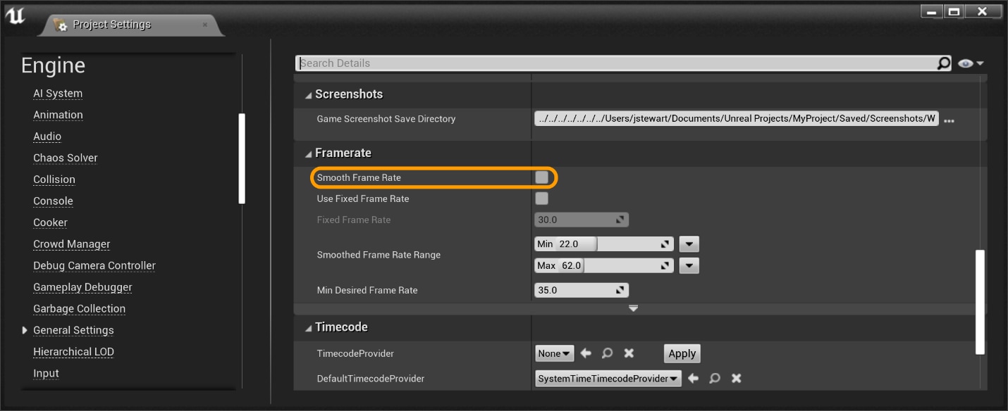
Alternatively, you can ensure bSmoothFrameRate is set up to fake everywhere it appears in Engine\Config\BaseEngine.ini and your project's DefaultEngine.ini . You can also add together bForceDisableFrameRateSmoothing=true to the [/Script/Engine.Engine] section of your project's DefaultEngine.ini .
Next, plow off VSync. Once manner to practice this is with the -novsync command-line parameter. Adding this to our previous example gives the post-obit:
UE4Editor.exe ShooterGame -game -nosound -noailogging -noverifygc -novsync Lastly, run your build and verify your resolution in the log file. Resolution is, of course, one very important factor in GPU operation, and it is worth verifying that information technology is what you wait. Open up the log file for your build and look for a line like the following:
LogRenderer: Reallocating scene render targets to support 2560x1440
Repeatable profiling
This department contains tips for getting consistent results when profiling, and so that you can better determine if a potential optimization actually improved performance.
Profiling from a single location
One way to contour is past going to the same location in your level.
A Actor Start actor tin be used to spawn directly to a specific location upon launch. This can be dragged into the scene through the editor.
If you have no way to modify the scene in editor mode, or would like to teleport while in-game, then y'all can use the UCheatManager BugIt tools. Annotation: BugIt tools are only available in non-shipping builds.
To teleport using BugIt:
- First open up a console window. In-editor this is attainable via Window->Developer Tools->Output Log. If y'all are in-game, utilize panel command
showlog. - Blazon
BugItinto the console. The beginning line in the output string should look like this:BugItGo 10 y z a b c. - This
BugItGocommand tin can exist pasted into the console to teleport to the electric current location from anywhere.
Reducing racket in profiling results
When attempting to optimize the execution time of a workload, we need to be able to reliably measure the fourth dimension a certain workload takes. These measurements should have as trivial dissonance as possible. Otherwise, we cannot tell whether it ran faster because of our optimization or considering some random number generator decided to spawn fewer particles (for example).
UE4 has some built-in functionality to help with this. The -criterion command-line argument causes UE4 to automatically change sure settings to exist more friendly to profiling. The -deterministic argument causes the engine to use a fixed timestep and a fixed random seed. Y'all tin can then use -fps to prepare the fixed timestep and -benchmarkseconds to have the engine automatically shut downwardly afterward a fixed number of timesteps.
Beneath is an example of using these arguments with a Test build of the Infiltrator demo:
UE4Game-Win64-Examination.exe "..\..\..\InfiltratorDemo\InfiltratorDemo.uproject" -nosound -noailogging -noverifygc -novsync -criterion -benchmarkseconds=211 -fps=60 -deterministic In the above case, benchmarkseconds is not wall-clock seconds (unless every frame of the demo runs at exactly 60 fps). Rather, it runs 211×lx=12,660 frames using a fixed timestep of ane/lx=sixteen.67 milliseconds. This ways that, if y'all have your project gear up to run a photographic camera flythrough on startup, it will accelerate through the flythrough using stock-still timesteps and a fixed random seed. It volition then shutdown automatically after a fixed number of frames. This can be useful in gathering repeatable average frame time data for your level.
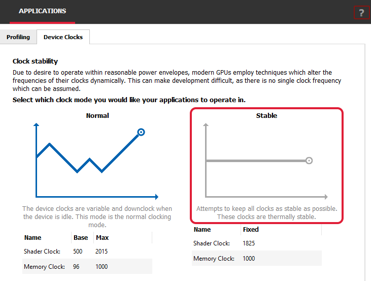
Another technique for helping reduce noise in profile results is to run with fixed clocks. Most GPUs have a default power management organization that switches to a lower clock frequency when idle to save power. But this trades lower ability consumption for performance and can introduce racket in our benchmarks, equally the clocks may not scale the same way between runs of our awarding. You may set up the clocks on your GPU to reduce this variance. Many third-party tools exist, but the Radeon Developer Panel that comes with the Radeon GPU Profiler has a Device Clocks tab under Applications which tin be used to set a stable clock on AMD RDNA™ GPUs, as shown below:
Getting dorsum to reducing variability in UE4, you lot may find that some things do non obey the fixed random seed from the -deterministic command-line statement. This was the case for some particles in the Infiltrator demo. These particles were causing a noticeable amount of noise in our benchmarks.
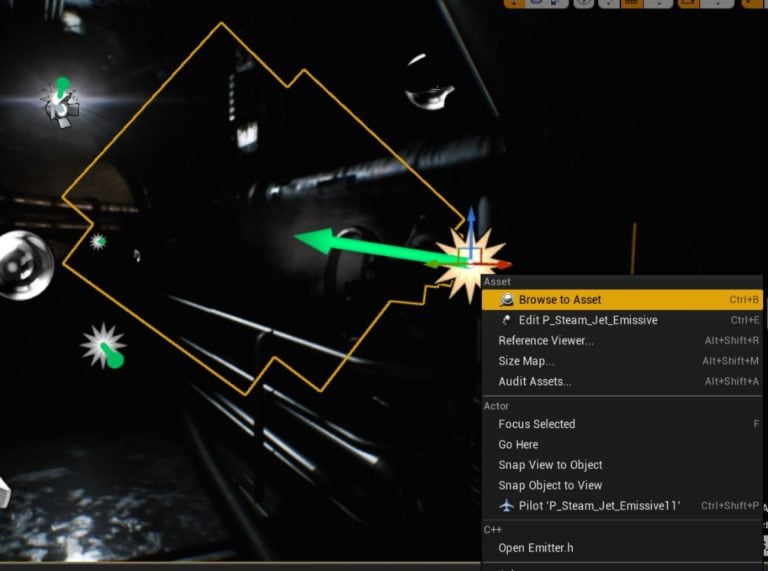
The solution to reducing particle dissonance is to brand the Random Number Generators used a fixed seed. This is how yous make the particles deterministic in just 2 clicks:
1- Right click on the emitter of particles and so click on "Browse to Asset"
2- Once the emitter nugget gets selected in the Content Browser, correct click on it and select "Convert To Seeded"
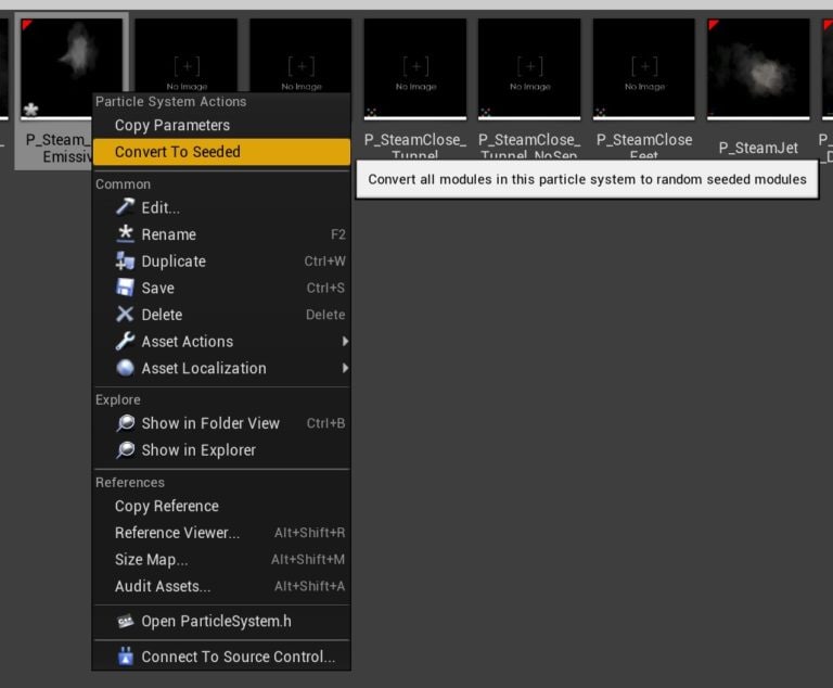
That'south information technology! You can as well select all your emitters in the Content Browser and convert them all at once. Once that has been done the noise will be much reduced and information technology should be very piece of cake to evaluate your optimizations.
Note: If you are using Niagara particles, look for "Deterministic Random Number Generation in Niagara" in the official UE4.22 release folio: https://www.unrealengine.com/en-U.s.a./blog/unreal-engine-iv-22-released
Consider making your own test scene
Optimizing an effect requires trying many experiments, and every iteration takes time. We need to rebuild the game, cook the content, etc. UE4 features like melt on the fly (COTF) can assist with this. But information technology tin as well be useful to isolate the effect or technique you are optimizing into a small application.
If only we could generate such an app easily! Fortunately, Unreal comes with a characteristic called Migrate for that. It extracts a certain asset with all its dependencies and volition import it in any other project. In this case, for the sake of creating a small-scale app, we would migrate the effect into an empty project.
Official documentation on migrating assets: https://docs.unrealengine.com/en-The states/Engine/Content/Browser/UserGuide/Migrate/alphabetize.html
CPU-jump or GPU-spring?
When getting started with performance profiling in UE4, it is of import to know where the primary operation bottlenecks are when running on the target platform. Depending on whether the clogging lies on the CPU or GPU, we may go in orthogonal directions with our functioning analysis.
After taking a performance capture with the Radeon Developer Panel (RDP), these details are available in the Radeon GPU Profiler (RGP) from the Overview->Frame Summary view.
The following shows an extreme CPU-bound example, created by adding CPU busy piece of work to UE4, followed by a GPU-bound scene.
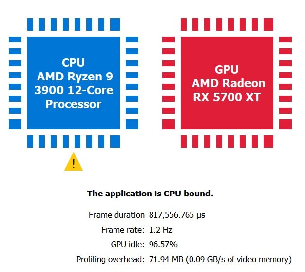
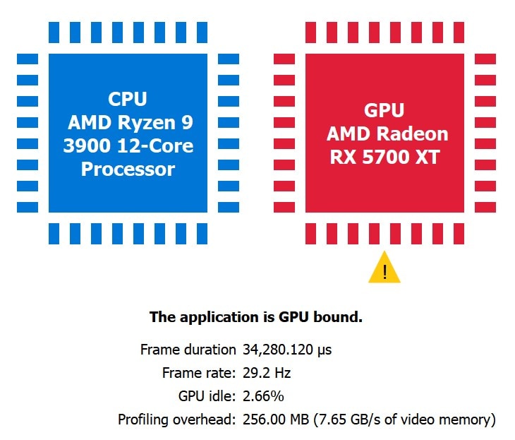
A good sanity test to check if the application is indeed CPU bound is to scale up the render resolution. For example, if the GPU workload is increased by setting r.ScreenPercentage from 100 to 150 and RGP shows the same CPU bound result as before, that is a strong indication the app is thoroughly CPU bound.
Once we decide if we are GPU-bound or CPU-bound, we may decide to diagnose further with RGP (if nosotros are GPU-bound) or switch to other tools like AMD μProf (if nosotros are CPU-bound). As mentioned earlier, this version of the guide is focused on the GPU, so we will now discuss how to make up one's mind where the GPU's fourth dimension is being spent.
Using RGP
The Radeon™ GPU Profiler (RGP) is a very useful tool for profiling on RDNA GPUs. To capture with RGP using UE4, we must run UE4 on either the D3D12 RHI or the Vulkan RHI. This guide will use D3D12 for its examples. You can invoke the D3D12 RHI either by running the UE4 executable with the -d3d12 command-line statement or by changing the default RHI in the editor: Edit->Project Settings…->Platforms->Windows->Default RHI to DirectX 12.
Before capturing with RGP, uncomment the post-obit line in ConsoleVariables.ini : D3D12.EmitRgpFrameMarkers=1 . This ensures that any UE4 code wrapped in a SCOPED_DRAW_EVENT macro appears as a useful marking in RGP.
Notation: if you are using a Test build, either ALLOW_CHEAT_CVARS_IN_TEST in Build.h so that ConsoleVariables.ini will exist used in Test builds or add a [ConsoleVariables] section to your project's DefaultEngine.ini :
[ConsoleVariables] D3D12.EmitRgpFrameMarkers=one
RGP and UE4 instance
This section uses one of our UE4 optimization patches on GPUOpen to demonstrate using RGP to profile. This instance reduces frame time by 0.2ms (measured on Radeon 5700XT at 4Kane). 0.2ms may non seem like much at first, but if yous are targeting 60fps for your game, 0.2ms is roughly 1% of your 60-Hz frame budget.
If yous accept the patch and desire to reproduce the results in this section, first apply the console to disable the optimization: r.PostProcess.HistogramReduce.UseCS 0
After taking a functioning capture with RDP, these details are available in RGP from the Events->Event Timing view. If y'all are emitting RGP perf markers, yous tin can quickly navigate to the marking that we are investigating by searching for " PostProcessHistogramReduce ".

Nosotros tin can see that the DrawIndexedInstanced() phone call takes 211us to complete. We tin do meliorate!
To inspect the details of the pixel shader running on the GPU, right-click on the draw phone call, select "View in Pipeline State" and click on PS in the pipeline.
The Data tab shows that our pixel shader is only running 1 wavefront and only taking up 32 threads of that wavefront. On GCN GPUs and higher up, this kind of GPU workload will execute in 'partial waves' which means the GPU is beingness underutilized.
The ISA tab will give us the exact shader instructions that are executed on GPU hardware as well every bit VGPR/SGPR occupancy. The ISA view is also useful for other optimizations similar scalarization which are non covered here (https://flashypixels.wordpress.com/2018/eleven/10/intro-to-gpu-scalarization-part-1/)
Viewing the HLSL source ( PostProcessHistogramReduce.usf ) for this shader shows that at that place is a lengthy loop that nosotros need to parallelize if we want to maximize the GPU hardware and eliminate any partial waves. We did this by switching to a compute shader and leveraging LDS (local data store/groupshared memory) – a hardware feature bachelor on modern GPUs which support Shader Model v.
Next, we can enable our optimization to encounter the performance bear on: r.PostProcess.HistogramReduce.UseCS 1
After taking another functioning capture with RDP and going dorsum to the Effect Timings view in RGP:

The fourth dimension taken for the dispatch is 7us – for a whopping 96% performance uplift! The majority of the time taken is at present in the bulwark which is unavoidable as our PostProcessHistogramReduce pass has a data dependency on the prior PostProcessHistogram pass.
The reason for this operation gain is executing shorter loops, leveraging LDS for reduction and using load instead of sample (image loads go through a fast path on RDNA). Going to the ISA view shows u.s.a. the new LDS work happening within ds_read* and ds_write* instructions.
1 – System Configuration: Ryzen ix 3900, 32GB DDR4-3200, Windows 10, Radeon Software Adrenalin 2022 Edition 20.2.two, 3840×2160 resolution
Built-in profiling tools
This department covers the built-in UE4 profiling tools. These can serve every bit a supplement to profiling with RGP.
UE4 stat commands
A list of all stat commands is officially documented here: https://docs.unrealengine.com/en-Us/Engine/Performance/StatCommands/alphabetize.html
The most important commands pruned from the higher up list:
-
stat fps: Unobtrusive view of frames per second (FPS) and ms per frame. -
stat unit: More in-depth version ofstat fps:- Frame: Total time to finish each frame, similar to ms per frame
- Game: C++ or Blueprint gameplay operation
- Depict: CPU render fourth dimension
- GPU: GPU render time
- RHIT: RHI thread fourth dimension, should exist but under the current frame time
- DynRes: Shows the ratio of primary to secondary screen percentage, separately for viewport width and peak (if dynamic resolution is enabled)
-
stat unitgraph: Shows the 'stat unit of measurement' data with a real-fourth dimension line graph plot. Useful for detecting hitches in otherwise smooth gameplay. -
stat scenerendering: Good for identifying bottlenecks in the overall UE4 rendering pipeline. Examples: dynamic lights, translucency price, depict telephone call count, etc. -
stat gpu: Shows "live" per-laissez passer timings. Useful for shader iteration and optimization. Y'all may have to preparer.GPUStatsEnabled 1for this to work. Developers with UE4 source code may zoom in on specific GPU work with theSCOPED_GPU_STATmacro. -
stat rhi: Shows retentiveness counters, useful for debugging retentivity force per unit area scenarios. -
stat startfileandstat stopfile: Dumps all the real-fourth dimension stat information inside the first/stop duration to a.ue4statsfile, which can be opened in Unreal Frontend: https://docs.unrealengine.com/en-The states/Engine/Deployment/UnrealFrontend/alphabetize.html
GPU Visualizer
The stat commands are great for a real-time view of operation, merely suppose you find a GPU clogging in your scene and wish to dig deeper into a single-frame capture.
The ProfileGPU control allows you expand i frame's GPU piece of work in the GPU Visualizer, useful for cases that require detailed info from the engine.
Some examples:
- In
stat gpunosotros run across Translucency being slower thanBasePasspast one ms. In GPU Visualizer, we then observe a translucent mesh that takes about 1ms. We can choose to remove or optimize this mesh to residuum time taken for opaque and translucent draws. - In
stat gpuwe meet both Shadow Depths and Lights->ShadowedLights costing us frame fourth dimension. In GPU Visualizer, nosotros then place an expensive dynamic low-cal source past name. We can choose to brand this a static light.
For the GUI version, gear up r.ProfileGPU.ShowUI to 1 before running ProfileGPU .
For more details, bank check out the official documentation: https://docs.unrealengine.com/en-US/Engine/Performance/GPU/alphabetize.html
We highly recommend using RGP in lieu of GPU Visualizer as your profiling workhorse for RDNA GPUs. RGP can have the same workflow as in the above examples. With RGP, you arrive-depth GPU operation captures with more accurate timings and low-level ISA analysis.
FPS Chart
Useful for benchmarking over a long period of time, getting stat unit times over the duration. Results get placed in a .csv file that can be plotted in the CSVToSVG Tool: https://docs.unrealengine.com/en-US/Engine/Performance/CSVToSVG/alphabetize.html
Console command to toggle: startfpschart and stopfpschart
Optimizing in Unreal Engine 4
This section presents general advice for the optimization of your content and shaders in UE4.
Optimize your geometry
Skilful optimization practice means fugitive over-tessellating geometry that produces modest triangles in screen space; in general, avert tiny triangles. This means that keeping your geometry in cheque is an of import gene in coming together your functioning targets. The Wireframe view manner accessible through the editor is a great outset look at the geometric complexity of objects in your scene. Note that heavy translucency can slow down the Wireframe view mode and makes it look more crowded and less helpful. RenderDoc too shows wireframe.
LODs in UE4 are an important tool to avoid lots of tiny triangles when meshes are viewed at a altitude. Refer to the official documentation for details: https://docs.unrealengine.com/en-US/Engine/Content/Types/StaticMeshes/HowTo/LODs/index.html
Optimize your describe calls
UE4 calculates scene visibility to choose objects that will not appear in the final paradigm of the frame. Yet, if the postal service-culled scene still contains thousands of objects, and then describe calls tin can become a operation event. Even if nosotros return meshes with depression polygon count, if there are as well many draw calls, it can become the primary performance bottleneck considering of the CPU side price associated with setting up each depict call for the GPU. Both UE4 and the GPU commuter do work per draw call.
Withal, reducing depict calls is a balancing act. If you determine to reduce draw calls by using few larger meshes instead of many small ones, y'all lose the alternative granularity that you become from smaller models.
Nosotros recommend using at to the lowest degree version 4.22 of Unreal Engine, to get the mesh drawing refactor with auto-instancing. See the GDC 2022 presentation from Epic for more than details: https://www.youtube.com/watch?five=qx1c190aGhs
UE4'southward Hierarchical Level of Detail (HLOD) system can replace several static meshes with a unmarried mesh at a distance, to help reduce draw calls. See the official documentation for details: https://docs.unrealengine.com/en-United states/Engine/HLOD/index.html
The ' stat scenerendering ' command tin can be used to check the draw call count for your scene.
Optimize your GPU execution
We covered one example of optimizing GPU execution in the RGP and UE4 Instance section earlier in the guide. We will cover another in the GPUOpen UE4 Optimization Case Study section. This section covers some built-in tools and workflows to help optimize GPU execution in UE4.
Optimization viewmodes
The UE4 editor has many visualization tools to help with debugging. The most notable of these for debugging performance would exist the Optimization Viewmodes. For an overview of the different modes, please meet the official documentation: https://docs.unrealengine.com/en-US/Engine/UI/LevelEditor/Viewports/ViewModes/index.html
- If your scene contains multiple low-cal sources with large source radius, and so you might want to check Light Complexity to optimize overlapping lights.
- For scenes with static lighting, Lightmap Density would evidence the texel resolution used during baked lighting for an Actor. If you lot accept a small object in the scene which takes up a pocket-size pixel area on the screen and that shows every bit red (high density), then information technology could be optimized. Clicking on the Role player, and change Lighting->Overriden Low-cal Map Res to a lower value. The actual performance toll here is in the retention usage of the Lightmap and/or Shadowmap (depending on the light type used).
- Static Shadowmaps can but be allowed four contributing lights per texel. Any excess stationary lights that overcontribute to a region tin exist visualized in Stationary Light Overlap. UE4 enforces this by irresolute backlog stationary lights to movable, marking them with a carmine cross and visualizing the overlap as a red region in Stationary Light Overlap. Since movable lights are very expensive, we tin can optimize excess lights by reducing radius or turning off static shadowing in Light->Cast Shadows.
- Shader Complexity uses a static analysis of the number of shader instructions executed per pixel to make up one's mind pixel price. Equally a supplement to this, we recommend Events->Wavefront occupancy and Overview->Most expensive events views in RGP to become a summary of where your frame time is going.
- Scenes with heavy translucency, leafage, or particle effects will render pixels with loftier values in Overdraw. If the boilerplate overdraw (marked by OD in the color ramp) stays at high values for most of your application then further optimization may be required.
Optimize your screen pct
Upscaling is a technique in which an application renders nigh of its frame at reduced resolution. And then, near the end of the frame, the application enlarges the rendered prototype to the desired output resolution. Rendering at lower resolution costs fewer shaded pixels while simultaneously reducing memory demands. This can result in significant performance savings without introducing much risk into your development or content pipelines. The trade-off is that rendering at a lower resolution can lead to less detailed terminal images. Various upscaling methods have been developed to minimize the reduction in quality from rendering at a lower resolution. Stock UE4 implements two separate upscaling algorithms, one spatial and one temporal, which are both controlled past the panel variable r.ScreenPercentage.
Assigning whatever value to this console variable which is greater than 0.0 and less than 100.0 volition automatically configure UE4 to upscale your project. The specified value is treated as a percentage multiplier of target resolution. For case, if your target resolution is 2560×1440 andr.ScreenPercentage is set to 75.0, almost of your frame will render at 1920×1080, merely upscaling to 2560×1440 well-nigh the end of the frame.
UE4 Spatial Upscaling
Spatial Upscaling is the default upscaling method employed past UE4. Spatial upscalers are minimally invasive and direct aggrandize a single image without requiring any additional information or context. In this respect, using a spatial upscaler is a lot similar resizing a picture in an image editing tool. UE4'south Spatial Upscaler has exceptional operation characteristics but its quality impact may exist significant when using lower resolutions compared to alternative upscaling solutions.
UE4 Temporal Upscaling
Temporal Upscaling is not UE4's default method of upscaling. In order to configure UE4 to utilise Temporal Upscaling, assign the value of 1 to the console variable r.TemporalAA.Upsampling. Temporal Upscaling in UE4 is applied equally part of the Temporal Anti-Aliasing algorithm (TAA), and as a upshot, TAA must be enabled for Temporal Upscaling to be used. Temporal upscalers are more complex than their spatial counterparts. At a loftier level, Temporal upscaling typically renders every frame at a different sub-pixel offset, and and so combines previous frames together to class an upscaled last image.
Non only is the algorithm itself more circuitous, but motion vectors must be present and tracked across multiple frames to attain high quality results. Additionally, UE4 Temporal Upscaling cannot render equally much of the frame at reduced resolutions every bit Spatial Upscaling tin, because UE4 Temporal Upscaling must always occur during the application of TAA. Therefore some post-process operations will however render at full resolution even when UE4 Temporal Upscaling is employed. UE4 Temporal Upscaler produces sizeable performance gains over native-resolution rendering, but its complexity may make information technology more expensive than alternative upscaling solutions. However, the quality of resulting images can be very loftier.
FidelityFX Super Resolution 1.0
Researchers at AMD take developed an exciting additional option for upscaling in UE4. We call it FidelityFX Super Resolution 1.0, or FSR i.0 for short. FSR 1.0 uses a collection of cut-border algorithms with a item accent on creating high-quality edges, giving large performance improvements compared to rendering at native resolution directly. FSR 1.0 enables "applied performance" for costly render operations, such as hardware ray tracing. FSR i.0 is a spatial upscaler, which ways it has the same minimally invasive nature and infrequent performance characteristics as UE4's Spatial Upscaler.
It is recommended to expose quality presets for FSR 1.0 as follows:
- Ultra Quality (77% screen pct)
- Quality (67% screen per centum)
- Balanced (59% screen percentage)
- Performance (l% screen percentage)
FSR 1.0 will run on a wide variety of GPUs and is completely open source on GitHub. FSR 1.0 can be integrated into your UE4.27.i (or higher) project with our FSR plugin, or by applying this FSR patch (patch requires you to be a UE-registered developer) for earlier versions. Cheque out FSR on GPUOpenfor more than information.
GPUOpen UE4 optimization case written report
At AMD, we maintain multiple teams with the primary focus of evaluating the performance of specific game titles or game engines on AMD hardware. These teams oft apply many of the methodologies presented in this document while evaluating UE4 products. In this section, we will take a guided look into the progression of some of those efforts. Easy integrations of the results from optimizations discussed in this department (and more than) are all available here.
Instance Report ane: Use ane triangle for fullscreen draws
Step i – Identify the optimization target
The life cycle of this optimization begins while evaluating a Radeon GPU Profiler (RGP) trace of Unreal Engine running on DX12. Before beginning any evaluation in RGP, ensure that UE4 is configured to emit RGP frame markers. This dramatically simplifies the task of navigating the sheer volume of data in RGP profiles and can be accomplished for DX12 by assigning the CVar value D3D12.EmitRgpFrameMarkers=one.
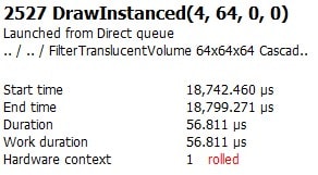
Under the OVERVIEW tab in RGP, at that place is a panel which presents a sorted listing of Almost expensive events. In ane capture, two specific events – correct next to each other under this sorting – stand out equally an optimization candidate:
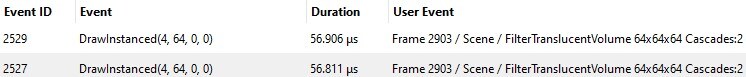
This pair stands out for a few specific reasons:
- The same Event with identical User Consequence information and very similar Duration happens twice back to back during the frame (Event ID 2527 vs Result ID 2529). This suggests these two Events are closely related to each other; they may even be the exact aforementioned operation against unlike inputs or outputs. If this is truthful, any savings yielded while optimizing the first event could besides impact the second… scaling our efforts by a factor of 2.
- There are 64 instances of this draw beingness rendered. This suggests any savings yielded optimizing 1 such draw could besides impact the other 63 instances, scaling our efforts by an additional factor of 64.
- Even a sub-microsecond improvement to each private draw could add upward very rapidly if scaled 128 times, and then allow's zoom in on this.
Footstep 2 – Empathise the optimization target
Earlier nosotros begin attempting to optimize this event, we should suspension to make sure we understand both what it does and how information technology does it. Nosotros will accomplish this by inspecting the functioning in Renderdoc. Before outset any debugging practise in Renderdoc, ensure that UE4 is configured to preserve shader debug information. If this information is available, Renderdoc will provide much more context nigh the execution of a given event. You lot tin achieve this by assigning the CVar value r.Shaders.KeepDebugInfo=1 . If y'all are turning this value on for the first fourth dimension, exist prepared to wait for completion of a lengthy shader compilation job the next time you lot launch Unreal.
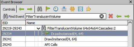
In the Most expensive events panel of RGP, right-clicking the desired event and selecting View in Event timing opens the EVENTS tab Event timing panel, and transports you directly to the targeted event.
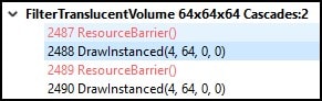
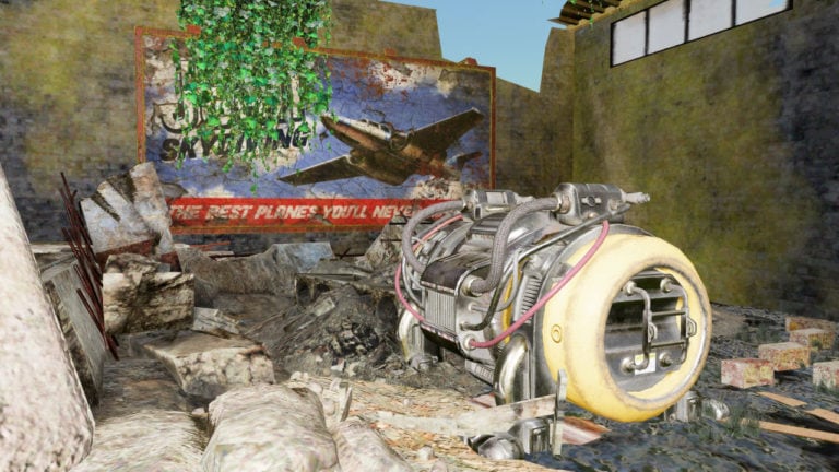
In this view, we tin can see that the event is part of a debug region titled FilterTranslucentVolume, and we will utilise this information to locate this event in Renderdoc moving forward.
In a Renderdoc capture of this scene, searching the Issue Browser for FilterTranslucentVolume directly transports u.s.a. to the Renderdoc representation of the targeted upshot.
With debug information preserved, we tin can directly see the full HLSL source with all relevant #include southward inline and all relevant #if s already evaluated for each stage of the rendering pipeline by clicking the View button at the top of the stage data panel in the Pipeline State tab. We tin also encounter the entry point in that source file for the target shader or view the raw disassembly if needed.
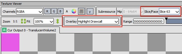
Inspection of the source files associated with each stage of this pipeline demonstrates that this event is reading pixels from a 64x64x64 3D texture and averaging the results into another 64x64x64 3D texture, one slice at a time. The Pixel Shader selects an appropriate slice within both input and output textures based on the Instance ID of the electric current depict. The Vertex and Geometry Shaders do no matrix manipulation confronting input vertices.
The combination of a iv vertex Draw with a Vertex Shader that does no matrix manipulation suggests that this operation is simply drawing a front-facing quad as a triangle strip. The additional context of what the Pixel Shader is doing suggests that quad is probably intended to cover the entire 64×64 region of a single piece of the output 3D texture. Inspection of the Input Assembler stage in Renderdoc – specifically the Mesh View visualization tool – verifies these expectations for the first instance drawn by this event. The 64×64 pink region in every slice of the Highlight Drawcall overlay in the Texture Viewer tab corroborates that information for each other instance, and across the unabridged output 3D texture space.
Step 3 – Ascertain the optimization plan
Armed with this information, we can finally begin trying to optimize! We start this process by returning to the Upshot timing panel in RGP. Selecting the targeted Upshot and so swapping to the Pipeline State tab at the top of the console provides additional information virtually this depict. Selecting the PS pipeline stage brings up additional information specifically about Pixel workloads.
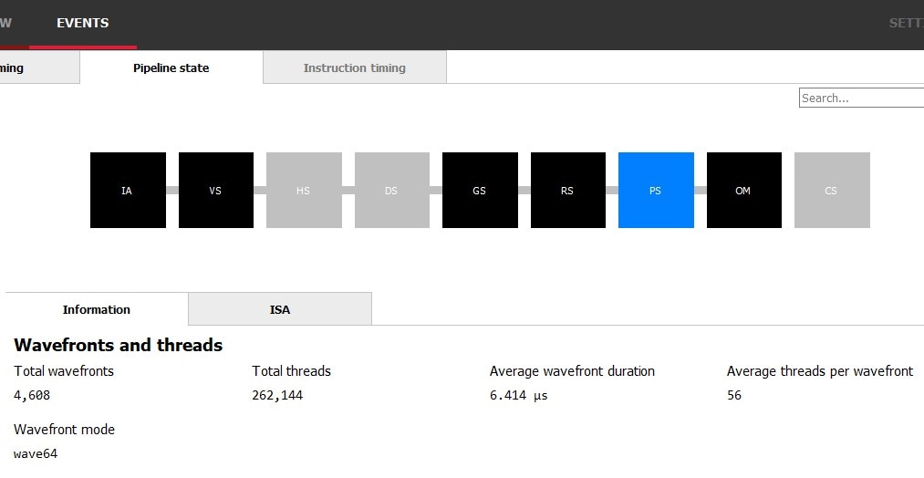
Here nosotros can come across a total of 262,144 unique pixel shader invocations, which aligns with our expectations from inspecting the result in Renderdoc: every pixel in a 64x64x64 3D texture should have been output, and 64x64x64 = 262,144. The other data presented here could exist apropos. AMD GPUs organize work into related groups chosen wavefronts. The wavefront mode for this effect is wave64, then under platonic circumstances in that location should exist 64 threads per wavefront; we simply realized 56 of those threads in the boilerplate wavefront during this event. This reality means nosotros may exist wasting possible cycles and represents a potential opportunity for optimization. Whether that potential can exist manifest depends entirely on why we're failing to realize 64 threads per wavefront.
At a loftier level, the organization of related piece of work into wavefronts normally produces highly efficient execution through SIMD. In this scenario, that organization besides comes with a drawback. Because the quad is rendered using two separate triangles, separate wavefronts are generated for the pixel work associated with each of those triangles. Some of the pixels near the boundary separating those triangles end up being organized into partial wavefronts, in which some of the threads are simply disabled because they represent pixels that are exterior of the active triangle. The relatively pocket-size dimensions of each private 64×64 output region exacerbates this phenomenon every bit a percentage of overall work. Unabridged documents accept been produced detailing causes behind this phenomenon. We encourage you to read some of the AMD whitepapers for additional information!
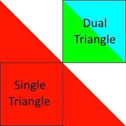
From hither, the solution to improve the efficiency of organizing existing pixel piece of work is relatively straightforward. Since the trouble results from the existence of a big pixel-space boundary between two triangles, eliminating that boundary eliminates the problem. While inspecting this event in Renderdoc, we learned that the entire 64×64 region represented by each slice of the render target is being output. Pixels that would fall outside that region are implicitly discarded earlier ever reaching the Pixel Shader stage of the rendering pipeline, and we tin can take reward of this fact to reconsider how we cover this region. The image to the right shows how we could fully cover this region (and so some) with a single triangle. While the exact coverage afforded by the Dual Triangle representation seems more prudent at first, the data we've nerveless and then far suggests that eliminating the purlieus between those 2 triangles may ultimately be more efficient.
Nosotros can also theorize an additional possible do good to this refactor. During inspection, we noted that the Pixel Shader is largely sampling pre-generated textures and averaging the results into the output return target. There is very little computational work going on here, and most of the expense for this kernel should present equally waiting on memory accesses. Eliminating the second triangle volition change the rasterization pattern of this quad, because individually generated wavefronts are no longer restricted to covering a unmarried triangle – one-half of the input and output regions. Removing this condition allows wavefronts to operate on entire blocks of compressed memory or unabridged scanlines of uncompressed retentiveness in unimpeded succession. This is likely to improve the benefits yielded by spatial caching on our memory accesses, and we expect we may see improvement in overall cache utilization as a result.
Step 4 – Implement the optimization programme
With the optimization plan in identify, it'south time to implement. We again employ the debug region from both RGP and Renderdoc to assistance us identify the appropriate location to brand this refactor in Unreal Engine source. Searching the source code for FilterTranslucentVolume produces a handful of results, including one which invokes the macro SCOPED_DRAW_EVENTF . That macro is producing the debug markers we see in both Renderdoc and RGP; we've institute our entry point. Inspecting the source to that office somewhen takes us to the function RasterizeToVolumeTexture in the file VolumeRendering.cpp , where we find ii things:
- The telephone call to
SetStreamSource, using the vertex buffer from the objectGVolumeRasterizeVertexBuffer. We'll want to evaluate how this object gets initialized and supersede that initialization with the vertices for our single, larger triangle. - The call to
DrawPrimitive. When we've replaced the quad equanimous of two triangles with a unmarried triangle, we'll likely need to tellDrawPrimitiveto reduce the number of primitives fatigued from 2 to 1 as well.
With our foot now firmly in the door, the rest of this implementation exercise is carried out in the patch available here.
Step 5 – Brand sure the optimized implementation works
Information technology is important to ensure the optimization works completely and correctly before you start measuring operation gains. Skipping this pace frequently results in apparent significant wins that are ultimately undercut when functional holes are later realized. Renderdoc remains the tool of pick here. Since we've already spent time evaluating and understanding the original implementation, knowing what to review in Renderdoc post-optimization is straightforward. We haven't touched any of the shaders, so we don't look problems in that location. We do need to ensure that the output of our new triangles completely covers every piece of the 3D texture, survives backface culling, and has appropriate texture coordinates. The Mesh View tool and Texture Viewer Overlays in Renderdoc make quick piece of work of this validation.
Pace vi – Clarify performance results
The start and most of import effect to evaluate is that we encounter performance savings on the event in question. This job is easily handled past returning to the Event timing panel of the EVENTS tab in RGP and clicking the Show details push in the meridian right corner of the panel. This expands the details pane, which includes the overall elapsing of the private task. In this case, we tin can see a reduction of well-nigh 20us.
Before – dual triangle quad (4 vertices)
After – unmarried triangle quad (3 vertices)
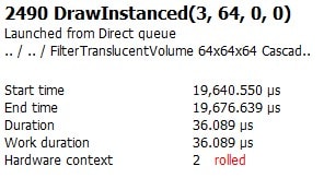
Because we previously identified that this exact event seems to happen twice, nosotros can also hands demonstrate that nosotros encounter those 20us savings twice. Great!
In that location is too value in ensuring we correctly understood why things accept gotten faster. Sometimes, additional savings come out of this exercise when you realize yous notwithstanding haven't fixed the outcome you ready out to fix. Nosotros will apply both RGP and Renderdoc in this evaluation. Since we have already used RGP to see the inefficient thread utilization of our wavefronts, information technology is easy to return to that view in the Pipeline state panel of the EVENTS tab and validate the boilerplate threads per wavefront of Pixel Shader work has increased. They have – all the manner 64, and this is exactly what we wanted to see. This indicates we have successfully eliminated all fractional wavefronts from this event equally a outcome of this operation.

We also see a hint here that our theorized improvement to cache utilization may have borne fruit. In addition to spawning fewer and more efficiently organized wavefronts, the average wavefront elapsing has simultaneously decreased from 6.414us to 5.815us. Withal, this data is anecdotal and does not prove anything. In club to get proof that enshroud utilization improved, we can inspect AMD-specific functioning counters.
Unfortunately, as of the time of this writing RGP does not all the same support streaming performance counters. Notwithstanding, latest versions of Renderdoc do, including AMD-specific operation counters! We can inspect this data in a Renderdoc capture of our scene by selecting Window > Performance Counter Viewer to open the associated tab. Clicking the Capture counters button opens a dialog which includes an AMD dropdown, from which we can select cache hit and miss counters for all enshroud levels.
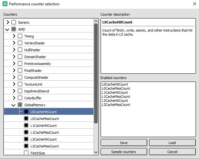
Later on clicking the Sample counters button, Renderdoc will re-render the scene with counters enabled. Adjacent to the Capture counters button in the Functioning Counter Viewer tab is a push that says Sync Views. Ensure that Sync Views is enabled, and then select the targeted event in the Issue Browser. If you already had the targeted event selected, select a different event and then simply go back. The Performance Counter Viewer tab will automatically scroll to and highlight the row containing counters for the targeted upshot.
By combining the enshroud hitting counts and enshroud miss counts, we tin can produce representations of constructive cache utilization as a percent of cache requests which were successful. That exercise was completed in excel for this optimization and the raw data is presented here:
| Dual-Tri | Single-Tri | DT Hit | DT Miss | ST Hitting | ST Miss | |
|---|---|---|---|---|---|---|
| L0 | 95.sixty% | 99.29% | 4426426 | 203518 | 3034589 | 21563 |
| L1 | 56.52% | 23.21% | 37413 | 28777 | 5092 | 16850 |
| L2 | 71.sixty% | 73.37% | 83457 | 33095 | 49350 | 17908 |
| Overall | 94.49% | 98.21% | 4547296 | 265390 | 3089031 | 56321 |
These results demonstrate pregnant overall improvement and testify hugely successful L0 utilization afterward applying this optimization. This assay of performance results indicates success across all criteria.
Stride 7 – Make sure aught else is broken
Unreal Engine is a big and complex lawmaking base, and sometimes it can be difficult to make targeted changes that don't accept side effects. Testing paradigms invariably change from project to project and from optimization to optimization, but a few tips to keep in mind:
- Use a debugger. Breakpoints can hands provide you with callstacks and context any fourth dimension anyone invokes lawmaking that you've inverse. Make sure you await it every time it happens.
- Pause down all identified invocations in Renderdoc using the same strategies outlined in Pace 2.
- Test more than one scene, and proceed in mind that if your project is dynamic… testing however images may exist insufficient to catch all bug.
- Static analysis may exist required depending on your apply case and target audition. Information technology's the hardest respond, simply sometimes it's also the best.
- Sometimes "shut plenty" is the same thing as "good plenty", specially if yous aren't distributing your changes externally. If your change produces artifacts to intermediate values in Renderdoc that are not noticeable in the final scene, you may not need to set up that.
- Sometimes an optimization is not intended to produce identical results as the original algorithm. Sometimes a slightly worse but significantly faster answer is a practiced tradeoff, especially for video games.
- Computing the Hateful Squared Mistake (MSE) is a valuable tool for objectively quantifying artifacts and making sound decisions about error tolerance. AMD Engineers ofttimes use Compressonator to help with this kind of analysis.
Executing this step properly is e'er important and tin sometimes increase the relative value of an optimization. While performing this do on the single-triangle optimization discussed hither, we identified many draws beyond the original pair that were positively affected by this optimization. Overall expected savings increased accordingly.
Further reading
Unreal Engine
Develop for Unreal Engine on AMD hardware with our plugin, performance and feature patches, including FidelityFX support.

Radeon™ GPU Profiler
RGP gives you unprecedented, in-depth access to a GPU. Easily analyze graphics, async compute usage, event timing, pipeline stalls, barriers, bottlenecks, and other performance inefficiencies.


Subsurface Handful in Unreal Forward Renderer (2017) – YouTube link
This talk discusses how subsurface scattering is implemented in Unreal Engine's forrad renderer. Considering UE4 implements subsurface scattering as a screen infinite effect, it wasn't bachelor on the forward path past default, so a new technique had to exist implemented, and one that had to however work with the UE4 material system and editor.

Developer Guides
Browse our programmer guides, and notice valuable advice on developing with AMD hardware, ray tracing, Vulkan, DirectX, UE4, and lots more.
FEMFX
A multithreaded CPU library for deformable fabric physics, using the Finite Element Method (FEM)


Developer Guides
Browse our developer guides, and detect valuable advice on developing with AMD hardware, ray tracing, Vulkan, DirectX, UE4, and lots more than.

Samples Library
Browse all our useful samples. Perfect for when you're needing to get started, want to integrate one of our libraries, and much more than.
Why not discover what else GPUOpen tin can offer you?
Source: https://gpuopen.com/unreal-engine-performance-guide/
Post a Comment for "Ue4 Can You Change the Level's Tick Interval"